|
| By Laurent Itti | itti@usc.edu | http://jevois.org | GPL v3 |
| |||
| Video Mapping: YUYV 640 520 25.0 YUYV 640 480 25.0 JeVois DemoDMP |
Module Documentation
As an optional hardware upgrade, one can install a global shutter sensor into JeVois (an OnSemi AR0135 1.2MP), which also includes on its custom circuit board for JeVois an inertial measurement unit (IMU). The IMU is a 9-degrees-of-freedom (9DOF) TDK InvenSense ICM-20948 (with 3-axis accelerometer, 3-axis gyroscope, and 3-axis magnetometer). This IMU also includes a digital motion processing unit (small programmable processor inside the IMU chip), which allows it to compute and filter quaternions directly inside the IMU chip.
This module only works with optional JeVois sensors that include an IMU! The base JeVois-A33 smart camera does not have an onboard IMU.
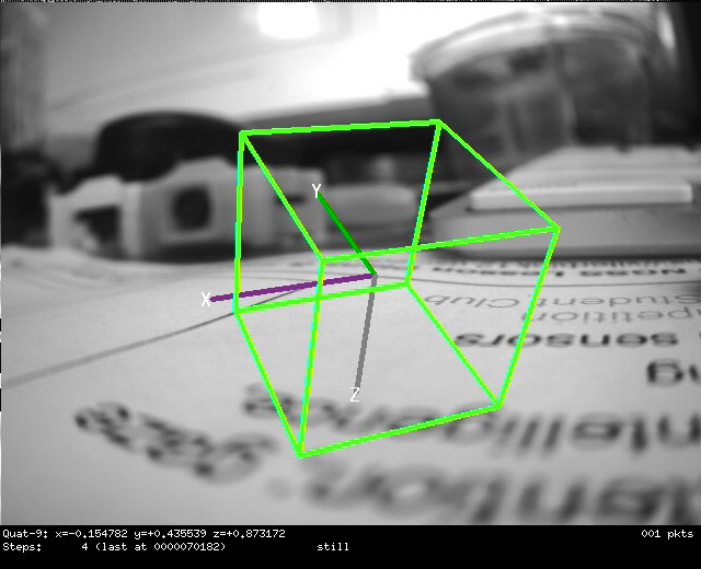
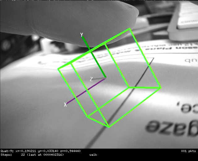
This module demonstrates the digital motion processing (DMP) mode of the IMU.
The specifications of this chip are quite impressive:
- 3-axis 16-bit accelerometer with full-range sensitivity selectable to +/-2g, +/-4g, +/-8g, and +/-16g.
- Accelerometer data rate from 4 Hz to 1125 Hz.
- 3-axis 16-bit gyroscope with full-range sensitivity selectable to +/-250dps (degrees/s), +/-500dps, +/-1000dps, and +/-2000dps.
- Gyroscope data rate from 4 Hz to 1125 Hz.
- 3-axis 16-bit magnetometer (compass) with wide range of +/-4900uT (micro Tesla).
- Magnetometer data rates 10 Hz, 20 Hz, 50 Hz, or 100 Hz.
- 16-bit temperature sensor with readout rate of up to 8 kHz.
- RAW data mode (get current sensor values at any time), buffered (FIFO) data mode (sensor values accumulate into a FIFO at a fixed rate), and digital motion processing mode (DMP; raw data is processed on-chip).
- On-chip digital motion processor (DMP) can compute, inside the IMU chip itself:
- quaternion 6 (uses accel + gyro),
- quaternion 9 (uses accel + gyro + compass),
- geomag quaternion (uses accel + compass),
- flip/pickup detection,
- step detection and counting,
- basic activity recognition: drive, walk, run, bike, tilt, still.
With quaternions computed on-chip, with an algorithm that gets sensor data at a highly accurate, fixed rate, and applies various calibrations, drift corrections, and compensations on the fly, one gets highly accurate real-time estimate of the sensor's pose in the 3D world and of how it is moving.
Note that communication with the IMU is over a 400kHz I2C bus, which may limit data readout rate depending on which data is requested from the IMU.
This IMU has 3 basic modes of operation (parameter mode, which can only be set in params.cfg):
- RAW: One can access the latest raw sensor data at any time using the getRaw() or get() functions. This is the simplest mode of operation. One disadvantage is that if you are not calling get() at a perfectly regular interval, there will be some time jitter in your readouts. The IMU does not provide any time stamps for its data.
- FIFO: In this mode, data from the sensor is piled up into a 1 kbyte FIFO buffer at a precise, constant rate (when all three of accelerometer, gyroscope, and magnetometer are on, the gyro rate determines the FIFO buffering rate). Main advantage is that you can then read out the data without having to worry about calling getRaw() or get() at a highly precise interval. But you need to be careful that the FIFO can fill up and overflow very quickly when using high sensor data rates.
- DMP: In this mode, data is captured from the sensor at an accurate, fixed rate, and is fed to the on-chip digital motion processor (DMP). The DMP then computes quaternions, activity recognition, etc and pushes data packets into the FIFO as results from these algorithms become available.
Low-level tweaking of the IMU and DMP
The ICM-20948 IMU chip is a very sophisticated and complex computer on its own right. There are many settings and modes that are supported. Unfortunately, the full documentation is not open. But you can obtain it after registration with TDK InvenSense. We provide the following user-level functions in the command-line interface of JeVois to allow you to get/set raw registers of the IMU and DMP:
- setimureg reg val - set raw IMU register reg to value val
- getimureg reg - get value of raw IMU register reg
- setimuregs reg num val1 ... valn - set array of raw IMU register values
- getimuregs reg num - get array of raw IMU register values
- setdmpreg reg val - set raw DMP register reg to value val
- getdmpreg reg - get value of raw DMP register reg
- setdmpregs reg num val1 ... valn - set array of raw DMP register values
- getdmpregs reg num - get array of raw DMP register values
The registers and values can be specified in decimal, hex (with prefix 0x), or octal (with prefix 0 - beware of this and be careful). The values returned are always in hex (with no prefix). Note that the above functions are not activated by default, to prevent mistakes by rookie users. To activate them, issue a setpar camreg 1 on the JeVois console.
For example, to set the output data rate (ODR) of the DMP quaternion-9; this is in DMP register DMP_ODR_QUAT9 = 168 (see definitions in file ICM20948_regs.H of the JeVois core software):
setpar camreg 1
getdmpreg 168 # shows default divider value of 5; ODR is DMP engine rate / (1 + divider)
setdmpreg 168 2
To see the effect, you should first turn on FSYNC as one of the DMP outputs (e.g., set dmp parameter to QF). Then turn on parameter pktdbg and turn on log messages to USB see how many quaternion packets (long packets that start with 4 0) you get between two FSYNC packets (short packets that start with 0 8 8 0). By default it is about 2 (with camera sensor at 25fps and DMP engine running at 56Hz). Then increase the arate and grate to 112 Hz. You should still get about 2 quaternion packets between two FSYNC packets. Finally, apply the above DMP register change. You should now see 4 quaternion packets between two FSYNC packets. Note that sometimes quaternion and FSYNC packets get combined.
As you experiment, keep in mind that the IMU can easily saturate the 400 kHz bandwidth of the i2c bus that connects it to the JeVois main processor. If you start getting errors in the console from IMUdata::parsePacket() then likely your data rate is too high for the i2c bus. One of the nice things about the DMP is that you can still run the quaternion computation very fast (e.g., at 450 Hz or even 1125 Hz) while maintaining a low output data rate.
| Parameter | Type | Description | Default | Valid Values |
|---|---|---|---|---|
| (ICM20948) mode | Mode | Data collection mode. RAW means that the latest available raw data is returned each time get() is called, hence timing may not be very accurate depending on how regularly get() is called. FIFO collects accel and gyro data at the exact rates specified by parameters arate, grate into a 1kb FIFO queue, and get() takes that data back from the FIFO. DMP runs the embedded digital motion processor on raw data, and accumulates resulting output data into the IMU's internal FIFO buffer at a precise, fixed rate. This parameter can only be set in a module's params.cfg file. | Mode::RAW | Mode_Values |
| (ICM20948) dmp | std::string | Requested DMP data. Only valid when mode is DMP. Use any string of letters including:A=acceleration, G=gyro, M=magnetometer (compass), R=quaternion 6 (uses accel + gyro), Q=quaternion 9 (uses accel + gyro + compass), E=geomag (uses accel + compass), P=flip/pickup detection, S=step detection, T=activity recognition, F=frame sync from video sensor, w=configure activity recognition for wearable, g=gyro calibration (always on when gyro used), m=compass calibration (always on when compass used), b=accel accuracy (always on when accel used), h=gyro accuracy (always on when gyro used), n=compass accuracy (always on when compass used). | QSPT | - |
| (ICM20948) pktdbg | bool | Send raw FIFO or DMP packets to console for debug/hacking purposes. | false | - |
| (ICM20948) arate | float | Accelerometer sampling rate (Hz), or 0.0 to disable accelerometer. Actual sample rate may differ because of finite and discrete divider settings. In FIFO mode, grate controls the data rate. | 30.0F | jevois::Range<float>(0.0F, 1125.0F) |
| (ICM20948) grate | float | Gyroscope sampling rate (Hz), or 0.0 to disable gyroscope. Actual sample rate may differ because of finite and discrete divider settings. In FIFO mode, grate controls the data rate. | 30.0F | jevois::Range<float>(0.0F, 1125.0F) |
| (ICM20948) mrate | MagRate | Magnetometer sampling rate (Hz), or Off to disable magnetometer, or Once to only get one measurement. You can repeatedly set this parameter to Once to obtain repeated measurements at your own pace. In JeVois Inventor, you need to alternate between Off and Once. In FIFO mode, grate controls the data rate. | MagRate::M50Hz | MagRate_Values |
params.cfg file# IMU mode configuration - these config are applied when the DemoIMU module starts # This is the only time the RAW vs FIFO vs DMP mode of operation can be selected. # This module only works with the Digital Motion Processor (DMP): mode = DMP # Set parameters for the IMU to work well in DMP mode: arate = 56 grate = 56 mrate = M50Hz # Select which computations the DMP will carry out: dmp = QSPT # Adjust sensitivity to get stable quaternions even on a camera with fan: abw = 12 arange = 16 gbw = 12 grange = 2000 tbw = 17 |
| Detailed docs: | DemoDMP |
|---|---|
| Copyright: | Copyright (C) 2018 by Laurent Itti, iLab and the University of Southern California |
| License: | GPL v3 |
| Distribution: | Unrestricted |
| Restrictions: | None |
| Support URL: | http://jevois.org/doc |
| Other URL: | http://iLab.usc.edu |
| Address: | University of Southern California, HNB-07A, 3641 Watt Way, Los Angeles, CA 90089-2520, USA |