JeVois Tutorials  1.20
JeVois Smart Embedded Machine Vision Tutorials
Share this page:
Making a motorized pan-tilt head for JeVois and tracking objects

Several JeVois machine vision modules detect and locate target objects in video, either based on their visual salience, on a specific color, on a specific type of shape (e.g., ArUco marker), or on a generic learned appearance. Some of these modules issue messages to the JeVois serial ports that indicate the coordinates of the objects that were found (and adding such messages to those which do not yet send them is a simple modification).

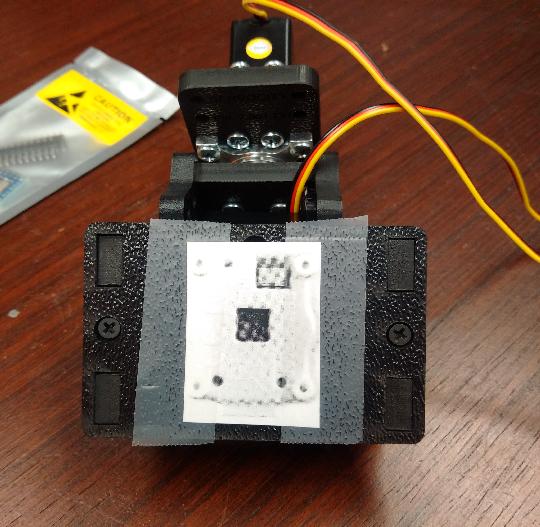
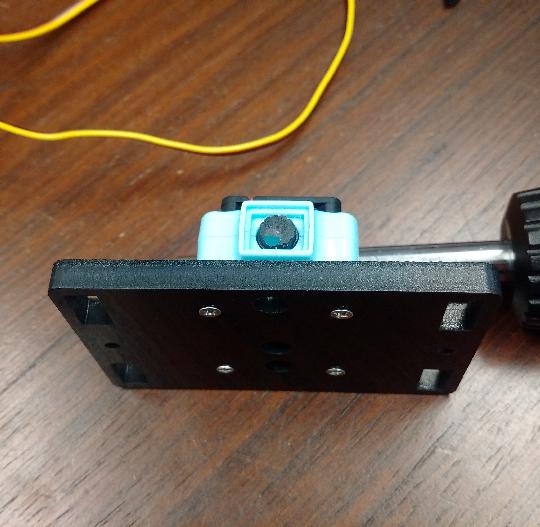
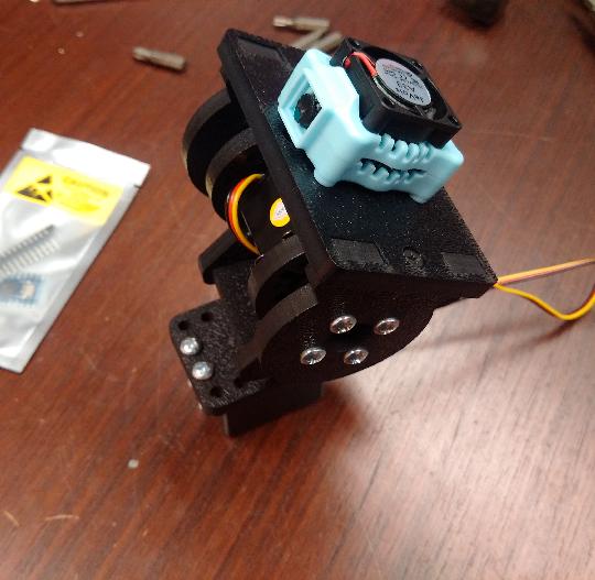
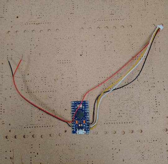
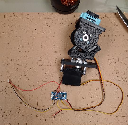
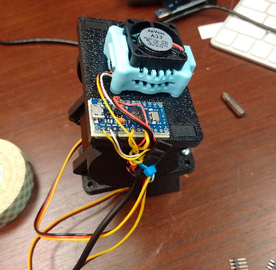
In this tutorial, we use a motorized pan-tilt head and a small Arduino-compatible board to control the pan-tilt head, so that it will always try to center the detected object in the camera's field of view. That is, we will use the coordinates issued by JeVois, to counter-rotate the pan-tilt head (onto which JeVois should be mounted) so as to center the objects of interest. The net effect will be that JeVois mounted on the pan-tilt head will track the objects of interest.

This tutorial is a direct extension, with more details, step-by-step instructions, and with pictures, of the Tutorial on how to write Arduino code that interacts with JeVois in the main JeVois documentation.

Getting started

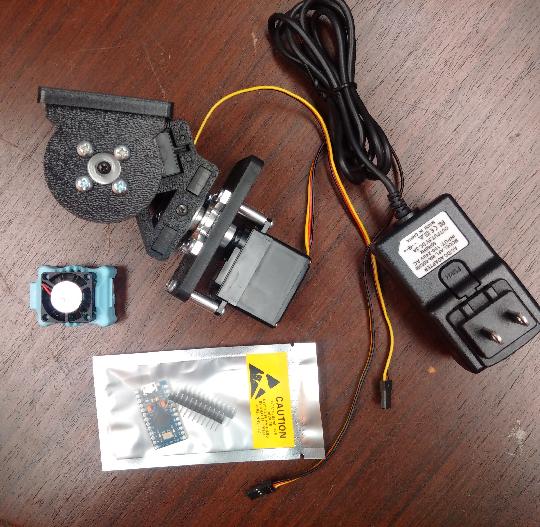
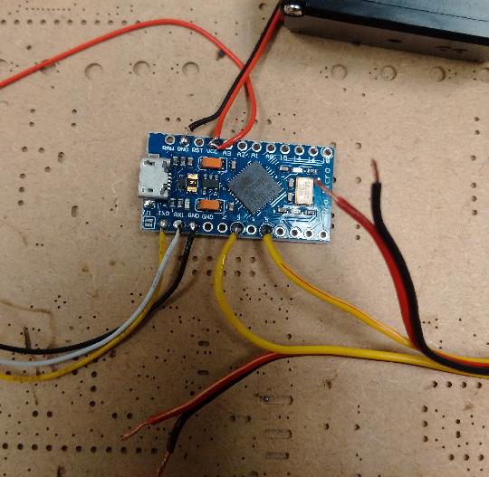
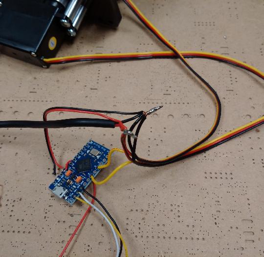
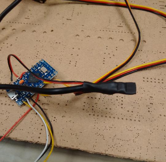
For this tutorial, we will use:

  • one JeVois smart camera;
  • one pan/tilt head actuated by two standard servo-motors (bought on eBay or any robotics shop);
  • one Arduino-compatible board with a 5V, 16MHz Atmega32u4 microcontroller. We use this specific one;
  • one 5V power supply rated at least 2A for the servos.

Basic plan of attack

  • We will power JeVois from a host computer using a mini-USB cable that will also let us see video from JeVois.
  • We will power the servos and the Arduino board from the 5V power supply.
  • We will connect the JeVois serial port (see Serial port user guide) to the Arduino's hardware serial port (pins TX1 and RX0). On the Atmega 32u4, these pins are referred to as the Serial1 port.
  • JeVois will send the coordinates of detected objects to the serial port.
  • The Arduino will receive the coordinates and will pan and tilt the head so as to try to center the object in the field of view. That is, it will track the object.

Hardware work

  • Assemble your pan-tilt head. Follow the instructions that came with it. This can take a while depending on which model you used.
  • Get the JeVois mounting template and print it at 100% scale.
  • Cut out one of the pictures in the template in which you can see the 4 mounting holes on the underside of JeVois.
  • Place the template on your pan-tilt head and drill 4 holes with a drill bit that is about 3mm in diameter. Alternatively, use the patterns described in JeVois-A33 case mounting guidelines to place your mounting holes.

  • Find 4 screws (M2.5 or USA 2-56 recommended) with a length chosen so that they stick out by 5mm (not more!) through the mounting plate.

  • Screw your JeVois smart camera to the mounting plate. As you hold your JeVois smart camera while you also thread the screws in, always remember to never push onto the center of the fan of JeVois (see JeVois Smart Camera Handling and Precautions). Do not over-tighten or you will just end up making big holes in the feet of your JeVois and you will then just need to try again, with bigger diameter screws.

  • Connect your JeVois micro-serial cable to your Arduino board as explained in Serial port user guide. On our small ProMicro board used here, there is no IOREF pin, so we just use VCC instead to provide a reference 5V voltage to JeVois, to be used as the level at which serial communications will operate.
  • Connect two wires to power your Arduino. Here we will use one black wire to GND and one red wire to VCC (since we will use a clean 5V power supply, we provide it directly to the Arduino's VCC and we bypass the RAW voltage input). Alternatively, you can power your Arduino from its micro-USB port (which we will do during programming), or you could use a 6V power supply (which will make your servos operate faster) and then connect that 6V to the RAW voltage supply pin of your Arduino (check specs of your Arduino to be sure).

  • Following the Tutorial on how to write Arduino code that interacts with JeVois, here we will connect the control line (yellow wire on our servos) of the pan servo to Arduino pin 3, and the control line of the tilt servo to pin 5. Any Arduino pin that supports PWM output would work (but you need to modify the Arduino code accordingly).

  • Connect 4 power wires together: 1 from the power supply, two for the servos, and one for the Arduino. Repeat for the 4 ground wires.

  • Insulate using heat-shrink tubing to make sure there will be no shorts as this contraption starts jerking around at high speeds.

  • Here, since we have so much room on the pan-tilt platform, we just tape the Arduino to is using double-stick tape (of the foamy type, for example Scotch 110P or 3M 4016). Just make sure you can still plug-in a micro-USB connector to program it. Here, we also use a zip tie through two holes that already were on the side of our pan-tilt head, to bundle and hold all the wires, so that we provide some strain relief (the solder joints will not be pulled upon as the head moves).

  • Plug in and check for sparks, burning smell, etc. If everything is quiet, you are ready to move on to the next step.

Programming the Arduino

  • Launch the Arduino software
  • Cut and paste the code below into the Arduino editor.
  • Power your pan-tilt head and connect its Arduino to your programming desktop using a micro-USB cable.
  • Select the correct target board (ours is compatible with Arduino Leonardo) and programming port (ours is the Leonardo direct programming). Compile and upload the software to your Arduino.
    Warning
    Your servos will move to their home position as soon as programming is complete, just be prepared for that.
  • Disconnect your programming computer. Power off your pan-tilt head for now.
1 // JeVois control steering or a pan/tilt head from the output of JeVois modules
2 //
3 // We handle messages "T2 <targetx> <targety>", "T1 <targetx>", "PANGAIN <gain>", and "TILTGAIN <gain>".
4 // targetx and targety are assumed to be in the -1000 ... 1000 range as output by the JeVois Kalman filters.
5 // Here we only do simple PD control under the assumption that target coordinates have already been filtered upstream.
6 #include <Servo.h>
7 // Pin for LED, blinks as we receive serial commands:
8 #define LEDPIN 13
9 // Serial port to use: on chips with USB (e.g., 32u4), that usually is Serial1. On chips without USB, use Serial:
10 #define SERIAL Serial1
11 // Pins for up to two servos:
12 Servo panservo;
13 #define PANPIN 3
14 Servo tiltservo;
15 #define TILTPIN 5
16 // Initial servo values in degrees:
17 #define PANZERO 90
18 #define TILTZERO 90
19 // With updates typically coming in at 60Hz or up to 120Hz, we will often need to move by a fraction of a
20 // degree. Hence we keep track of the pan and tilt values multiplied by SCALE. For the gains, a gain of 100
21 // means we will update servo angle by the 0.1*(target value/SCALE) degrees on each update. Higher gains mean
22 // larger angular updates.
23 #define SCALE 100
24 long pangain = 100;
25 long tiltgain = 100;
26 long panval = PANZERO * SCALE;
27 long tiltval = TILTZERO * SCALE;
28 // Buffer for received serial port bytes:
29 #define INLEN 128
30 char instr[INLEN + 1];
31 void setup()
32 {
33  SERIAL.begin(115200);
34  SERIAL.setTimeout(1000000);
35  pinMode(LEDPIN, OUTPUT);
36  digitalWrite(LEDPIN, LOW);
37 
38  panservo.attach(PANPIN);
39  panservo.write(panval / SCALE);
40  tiltservo.attach(TILTPIN);
41  tiltservo.write(tiltval / SCALE);
42  // We are ready to rock, disable logs and turn on serial outputs on JeVois platform:
43  SERIAL.println("setpar serlog None");
44  SERIAL.println("setpar serout Hard");
45 }
46 void loop()
47 {
48  digitalWrite(LEDPIN, LOW);
49  byte len = SERIAL.readBytesUntil('\n', instr, INLEN);
50  instr[len] = 0;
51  digitalWrite(LEDPIN, HIGH);
52  char * tok = strtok(instr, " \r\n");
53  int state = 0; int targx = 0, targy = 0;
54  while (tok)
55  {
56  // State machine:
57  // 0: start parsing
58  // 1: T2 command, parse targx
59  // 2: T2 command, parse targy
60  // 3: T2 command complete
61  // 4: T1 command, parse targx
62  // 5: T1 command complete
63  // 6: PANGAIN command, parse pangain
64  // 7: PANGAIN command complete
65  // 8: TILTGAIN command, parse tiltgain
66  // 9: TILTGAIN command complete
67  // 1000: unknown command
68  switch (state)
69  {
70  case 0:
71  if (strcmp(tok, "T2") == 0) state = 1;
72  else if (strcmp(tok, "T1") == 0) state = 4;
73  else if (strcmp(tok, "PANGAIN") == 0) state = 6;
74  else if (strcmp(tok, "TILTGAIN") == 0) state = 8;
75  else state = 1000;
76  break;
77 
78  case 1: targx = atoi(tok); state = 2; break;
79  case 2: targy = atoi(tok); state = 3; break;
80  case 4: targx = atoi(tok); state = 5; break;
81  case 6: pangain = atoi(tok); state = 7; break;
82  case 8: tiltgain = atoi(tok); state = 9; break;
83  default: break; // Skip any additional tokens
84  }
85  tok = strtok(0, " \r\n");
86  }
87  // Target coordinates are in range -1000 ... 1000. Servos want 0 ... 180.
88  // We also need to negate as needed so that the servo turns to cancel any offset from center:
89  if (state == 3 || state == 5)
90  {
91  panval -= (targx * pangain) / 1000;
92  if (panval < 5 * SCALE) panval = 5 * SCALE; else if (panval > 175 * SCALE) panval = 175 * SCALE;
93  panservo.write(panval / SCALE);
94  }
95 
96  if (state == 3)
97  {
98  tiltval += (targy * tiltgain) / 1000;
99  if (tiltval < 5 * SCALE) tiltval = 5 * SCALE; else if (tiltval > 175 * SCALE) tiltval = 175 * SCALE;
100  tiltservo.write(tiltval / SCALE);
101  }
102 }

Arduino code analysis

  • Line 10: Make sure you select the correct serial port. On an Atmega 32u4 (used here), pins 0 and 1 are handled by Serial1 (since Serial is for the USB serial port). On Arduino Uno and similar, you would use Serial instead.
  • Lines 31 - 45: We initialize the serial port, LED, and servos. We send a couple of commands to JeVois to instruct it to send serout messages to us and serlog messages to nobody.
  • Line 49: We read a serial string until an end-of-line marker.
  • Line 52: We split the first token from the received line, using space or some end of line character as token delimiter.
  • Line 54: We iterate over all tokens contained in the line. We will parse each token according to our current state in a simple state machine. The states are described in lines 56-67. We start in state 0.
  • Lines 68-84: Depending on state, we decode either a command or a number, and we switch to the appropriate next state, depending on what we have decoded so far.
  • Lines 89-94: We update the pan angle if the received command contained a pan value. We update the angle by a small fraction of the target X coordinate that was received, so that the head will move slightly towards the target. We do not move fully towards the target because that would move the head too fast given that serial commands are going to be received at 30Hz, 60Hz or more (see comments in lines 19-22).
  • Lines 96-101: Idem for tilt.

Tuning the pan-tilt head servo directions

Depending on the construction of your pan-tilt head, increasing the pan angle may turn the head rightwards or leftwards, and, likewise, increasing the tilt angle could turn the head up or down. To figure this out, we will first connect to the pan-tilt head manually. We will send hand-written commands to the head.

Before you start this, make sure you understand the following:

Now let's try the following:

  • Connect a mini-USB cable from a host computer to JeVois. Allow JeVois to boot up.
  • Do not start a video capture software yet. Instead, connect to JeVois over the serial-over-USB connection.
  • Issue the following command to configure the serout port to be the hardware 4-pin port of JeVois:
setpar serout Hard
  • Now let's move the pan-tilt head by hand. By default, it homes to standardized coordinates (0, 0). If we ask it to move to, say, (1000, 0), it should turn rightward. We will do that by using the serout command, which just forwards everything that is passed to it directly to the serout port. Hence, everything we type in a serout command will be sent to our Arduino.

    Note that the Arduino pan-tilt code is written to apply a small relative offset to a memorized pan-tilt location each time a serial command is received. Indeed, because the Arduino code will receive target coordinates up to 60 times per second, it would be too jerky to try each time to fully home onto the target. So, instead, the pan-tilt head will take a small step towards the target. The size of these steps is regulated by two control parameters in the Arduino code, PANGAIN and TILTGAIN, with default values of 100. Higher gain values will move the head more rapidly towards the target on each video frame.

serout T2 10000 0

As the command is received, the pan-tilt head should turn right by some amount. If it turns left, your pan gain should be negated. The Arduino code supports two commands, in addition to T2: PANGAIN and TILTGAIN. You can negate PANGAIN as follows if your pan-tilt head just turned left:

serout PANGAIN -100

Then try again

serout T2 10000 0

and the camera should now pan in the other direction than previously.

  • Repeat this process to adjust the tilt direction, now using commands like:
serout T2 0 10000

to tilt the camera up, and

serout TILTGAIN -100

Once you are done playing, make a note of what you did and you can later put these commands in a script.cfg file in the directory of the machine vision module you will be using (see how we did that in Tutorial on how to write Arduino code that interacts with JeVois).

Let's rock

We are ready to get that pan-tilt head controlled by JeVois.

  • Connect a mini-USB cable from JeVois to a host computer. Start a video capture software. Select one of the following:
    • YUYV 640x300 @ 60.0 fps - DemoSaliency
    • YUYV 320x254 @ 60.0 fps - Color-based ObjectTracker
    • YUYV 640x312 @ 50.0 fps - DemoSalGistFaceObj Saliency + Gist + Face + object recognition
    • any other that supports T2 or T1 serial outputs (see docs and/or source code and look for modules that support standardized serial messages).
  • Show some interesting object to JeVois and watch it track it.
  • You may want to increase the pan and tilt gains, which are very low by default. Higher values will move the pan-tilt head faster, so that it can better track fast-moving objects. The downside is that noisy inputs will also give rise to high jerky motions of the pan-tilt head.

    Try the following:

serout PANGAIN 500

(or use -500 if you need a negative gain for your particular pan-tilt head). See how much faster the head can track now.

Running with no USB output

Once you are comfortable with the operation of the algorithm, you can also try it as a true standalone machine vision system with no USB output. The steps are as follows:

  • Select a machine vision algorithm that supports processing with no USB output. Not all of them do. From the list of User guide to bundled vision modules and demos, we can select, for example the ObjectTracker and we see, towards the top of the page:
      Supports mappings with NO USB output:   Yes
    An example video mapping with no USB output (with NONE as USB pixel format) is also suggested:
      Video Mapping:   NONE 0 0 0.0 YUYV 320 240 60.0 JeVois ObjectTracker
  • If you are operating in low light, you may want to select a lower framerate than the suggested 60fps, so that the camera sensor will be allowed longer exposure time. Here we will use 30fps.
  • Let us first try interactively:
    • Power in the pan/tilt head
    • Connect JeVois to your host computer and allow it to boot
    • But do not start a video capture software
    • Connect to the JeVois command line interface as we have done above.
    • Issue the following:
      setmapping2 YUYV 320 240 30.0 JeVois ObjectTracker
      setpar serout Hard
      streamon
      which will load up the object tracker module and run it in the mode with no USB output. The setmapping2 command instructs JeVois to configure a given camera pixel format, resolution, and framerate, and to load the module ObjectTracker from Vendor JeVois. Because setmapping2 does not specify a USB output video format, the module will run with no USB video output. We then manually initiate video streaming using the streamon command when running with no USB output, because there is no video capture software that is going to initiate it. See Command-line interface user guide for details on setmapping2 and streamon.
    • Wave some object that was detected earlier in front of JeVois and your pan/tilt head should track it.
  • Once this works, we can configure JeVois to do this automatically at boot up:
    • Assuming that you are using the latest microSD image, just type usbsd in the command line interface, and a virtual USB flash drive named JEVOIS should appear on your host computer. See MicroSD card organization and files for details, towards bottom of the page.
    • Open the file JEVOIS:/jevois/config/initscript.cfg and add these lines:
      setmapping2 YUYV 320 240 30.0 JeVois ObjectTracker
      setpar serout Hard
      streamon
      initscript.cfg is executed by JeVois when it boots up. You can put in there any command that is valid for the command-line interface of JeVois.
    • Save and close the file and eject the JEVOIS virtual flash drive (drag to trash, click eject button, etc). JeVois will reboot.
    • After a few seconds, it should now start with the color-based pan/tilt control with no USB video output.
    • From this point on, you do not need your host computer anymore. You can power JeVois from a USB charger, USB battery bank, etc.
Note
Because we changed framerate here (from 60 fps while we were seeing the video over USB to 30 fps with no USB), the color tracking algorithm may need re-tuning. If it does not appear to track well, first try with 60 fps in your setmapping2 command, to match what we had before. You can then edit JEVOIS:/config/videomapping.cfg to change the framerate of the mode with USB output: Search for ObjectTracker and change this entry:
YUYV 320 254 60.0 YUYV 320 240 60.0 JeVois ObjectTracker
to
YUYV 320 254 30.0 YUYV 320 240 30.0 JeVois ObjectTracker
and see User guide to video modes and mappings for details about the format of video mappings. Next time you start your video capture software, be sure to select YUYV 320x254 at 30 fps. Then have a look at Tuning the color-based object tracker using a python graphical interface for tuning. You can save your tuned parameters to the file JEVOIS:/modules/JeVois/ObjectTracker/script.cfg as we did in this tutorial.

Additional activities

tiltgain
long tiltgain
Definition: ArduinoPanTiltTutorial.C:25
pangain
long pangain
Definition: ArduinoPanTiltTutorial.C:24
SCALE
#define SCALE
Definition: ArduinoPanTiltTutorial.C:23
INLEN
#define INLEN
Definition: ArduinoPanTiltTutorial.C:29
panval
long panval
Definition: ArduinoPanTiltTutorial.C:26
instr
char instr[INLEN+1]
Definition: ArduinoPanTiltTutorial.C:30
tiltservo
Servo tiltservo
Definition: ArduinoPanTiltTutorial.C:14
loop
void loop()
Definition: ArduinoPanTiltTutorial.C:46
tiltval
long tiltval
Definition: ArduinoPanTiltTutorial.C:27
panservo
Servo panservo
Definition: ArduinoPanTiltTutorial.C:12
LEDPIN
#define LEDPIN
Definition: ArduinoPanTiltTutorial.C:8
PANZERO
#define PANZERO
Definition: ArduinoPanTiltTutorial.C:17
TILTZERO
#define TILTZERO
Definition: ArduinoPanTiltTutorial.C:18
TILTPIN
#define TILTPIN
Definition: ArduinoPanTiltTutorial.C:15
PANPIN
#define PANPIN
Definition: ArduinoPanTiltTutorial.C:13
SERIAL
#define SERIAL
Definition: ArduinoPanTiltTutorial.C:10
setup
void setup()
Definition: ArduinoPanTiltTutorial.C:31